Michael Walczyk
Software Engineer & Media Artist
📷 Instagram
💻 Github
📝 LinkedIn
Polychora
💎 A 4D renderer and polychoron generator.
Description
Projections
After seeing videos of Miegakure gameplay, I became very interested in the idea of 4-dimensional rendering. It turns out that there are several ways to visualize higher dimensional objects. Perhaps the simplest method involves a projection from 4D to 3D. This is similar to how “traditional” 3D engines render objects to a 2D display surface (your screen). A 4D-to-3D projection can either be a perspective or parallel (orthographic) projection. However, instead of projecting objects onto a flat plane (as is the case in a 3D-to-2D projection), we project our 4-dimensional objects “onto” a 3-dimensional cuboid (in this case, the unit cube centered at the origin). From here, we simply perform the 3D-to-2D projection that we are used to.
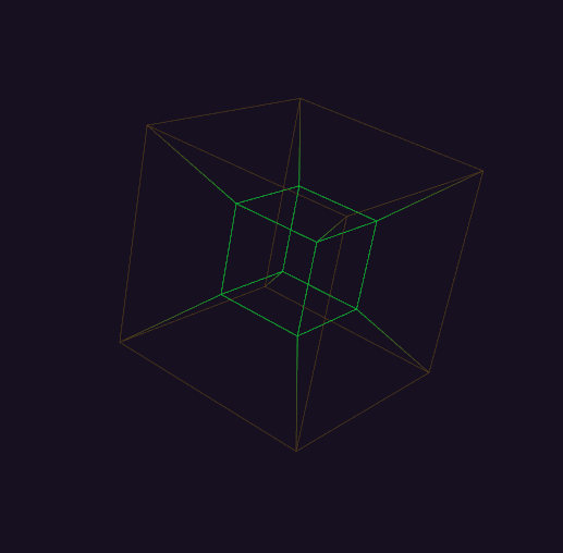
Most people are familiar with this form of visualization. When a 4D-to-3D perspective projection is applied to the 8-cell (also known as the hypercube or tesseract), the result is the familiar animation of an “outer” cube with a smaller, nested “inner” cube that appears to unfold itself via a series of 4-dimensional planar rotations. A wireframe render of the 8-cell is shown below. The reason why the inner cube appears smaller is because it is “further away” in the 4th dimension (the w-axis of our 4D coordinate system). In the image below, the colors serve as a rudimentary “depth cue,” helping us understand how different vertices and edges are related in the 4th dimension. If you are interested in this form of visualization, I highly recommend Steven Hollasch’s thesis, titled Four-Space Visualization of 4D Objects.
Slicing
An entirely different way to visualize 4-dimensional objects is via a “slicing” procedure, which produces a series of 3-dimensional cross-sections of the full 4-dimensional shape. This is analogous to “cutting” a 3D polyhedron with a 2-dimensional plane (think MRI scans). Luckily, much of the math carries over to 4D. In order to facilitate this process, meshes in polychora are represented by a “shell” of tetrahedra (more on this later).
Over the course of this research project, I have explored 2 different ways of generating polychora. Currently, shapes are generated in a fully procedural manner using combinatorics and QHull, a library for computing n-dimensional convex hulls. The coordinates of the vertices of all uniform + regular polychora are known and can be calculated via a set of even/odd permutations and changes-of-sign. For example, the 120-cell can be generated via the following “permutation table” (taken from the amazing catalog available at Eusebeia):
All permutations and changes-of-sign of:

  (2, 2, 0, 0)
  (√5, 1, 1, 1)
  (φ, φ, φ, φ^−2)
  (φ2, φ^−1, φ^−1, φ^−1)

Together with all even permutations and changes-of-sign of:

  (φ^2, φ^−2, 1, 0)
  (√5, φ^−1, φ, 0)
  (2, 1, φ, φ^−1)

where φ is the Golden Ratio.
I wrote a C++ header file for enumerating such permutations, together with help from the C++ standard template library and a header file from Eusebeia (for generating only the even permutations). Once the vertices are generated, we can pass them to QHull’s convex hull algorithm. Enabling the Qt “triangulation” flag results in a list of tetrahedral facets, which can be directly passed into the slicing pipeline. Alternatively, you can pass the Cn flag to QHull (where n is a small number epsilon), which forces the algorithm to merge coplanar facets. In my tests, a value of C0.001 sufficed. If you run QHull in this configuration on the vertices of the 120-cell, for example, you would end up with 120 non-simplical facets, each of which was a dodecahedron embedded in 4-space.
A row of rotating and “morphing” 600-cells is shown below:
Edges can be found in a rather brute-force manner that was suggested to me by Dr. Libor Vasa (see the “credits” section of this project). We can compute the pair-wise distance between all vertices in our permutation table and locate the smallest such distance. This value corresponds to the length of any edge of our polychoron. We iterate through our vertex pairs once more, keeping track of any pair whose distance is equal to (within an epsilon) the minimum distance that we calculated in the first pass. After removing duplicates (i.e. the edge [0, 1] is the same as edge [1, 0]), we have a list of all of the edges of our polychoron. Note that this only works for equilateral polychora, i.e. the uniform and regular polychora.
For my purposes, it was not necessary to enumerate the faces or cells of each polychoron, though this should be possible. In one of my email correspondences, Dr. Vasa described his method for enumerating the faces of the 120-cell. I’m including it below, should anyone else find this useful:
Each vertex lies in four cells, so chosing a vertex and three of its neighbors forms a hyperplane in which all the vertices of a single face must lie. I simply iterate over all vertices and select the ones that lie in the hyperplane. This way, I get many faces repeated, which I then filter out.
Previously, polychora were generated in a more ad-hoc manner, using a variety of modified “shape files” that I found on the internet (mostly from Paul Bourke’s website). You can find the corresponding code in an older, less polished version of this project, which was also written in Rust. I really wanted to get away from this approach, as I didn’t like the idea of storing “hard-coded” shape files in the project. Plus, generating shapes procedurally led to some very interesting challenges and insights. It also allowed me to explore many polychora that were previously inaccessible (since shapes files do not necessarily exist). However, the advantage of this “older” approach was that it gave immediate access to all of the connectivity information of each polychoron: vertices, edges, faces, and cells. However, because the resulting facets weren’t necessarily tetrahedral, I had to algorithmically “tetrahedralize” each mesh before rendering.
Tetrahedralization in 4-space is similar to triangulation in 3-space. In particular, any 3D convex polyhedron can be decomposed into tetrahedrons by first subdividing its faces into triangles. Next, we pick a vertex from the polyhedron (any vertex will do). We connect all of the other face triangles to the chosen vertex to form a set of tetrahedra (obviously, ignoring faces that contain the chosen vertex). This is not necessarily the “minimal tetrahedral decomposition” of the polyhedron (which is an active area of research for many polyhedra), but it always works. An example of this process for a regular, 3D cube can be found here.
So, I started with a 4D polychoron, whose “faces” (i.e. “cells”) are themselves convex polyhedra embedded in 4-dimensions. One by one, I “tetrahedralized” each cell. Together, the sum of these tetrahedra formed the desired 4-dimensional mesh. For example, the hypercube has 8 cells, each of which is a cube (this is why the hypercube is called the 8-cell). Each cube produces 6 distinct tetrahedra, so all together, the tetrahedral decomposition of the hypercube results in 48 tetrahedra. For a visual example of this procedure in 3-space, see the following Stack Overflow post: “How to Make an Icosahedron from 20 Tetrahedra”.
Regardless of the way in which the polychora are generated, one question remains: what is the importance of maintaining tetrahedral facets? It turns out that slicing a tetrahedron in 4-dimensions is much simpler than slicing the full cells that bound the polychoron. In particular, a sliced tetrahedron (embedded in 4-dimensions) will always produce zero, 3, or 4 vertices, which makes things quite a bit easier (particularly, when it comes to computing vertex indices for OpenGL rendering).
Implementation of the Slicing Procedure
Each mesh in polychora maintains a GPU-side buffer that holds all of its tetrahedra (each of which is an array of 4 vertices). The slicing operation is performed via a compute shader that ultimately generates a new set of vertices (the “slice”) for each tetrahedron. The same compute shader also generates draw commands on the GPU, which are later dispatched via glMultiDrawArraysIndirect. Essentially, each tetrahedron will generate its own unique draw command that renders either 0, 1, or 2 triangles, depending on whether the slicing operation returned an empty intersection (0), a single triangle (1), or a quad (2).
In the case where a tetrahedron’s slice is a quad, care needs to be taken in order to ensure a proper vertex winding order. This too is handled in the compute shader: the 4 vertices are sorted based on their signed angle with the polygon’s normal. This is accomplished via a simple insertion sort. In GLSL, this looks something like:
uint i = 1;
while(i < array.length())
{
    uint j = i;
    while(j > 0 && (array[j - 1] > array[j]))
    {
        vec2 temp = array[j];
        array[j] = array[j - 1];
        array[j - 1] = temp;

        j--;
    }
    i++;
}
After the slices are computed, the resulting object is rendered via a separate vertex / fragment shader that simply performs an orthographic 4D-to-3D projection.
Generating Colors
One interesting problem I encountered during this project was the task of generating procedural colors. Given the fact that we know which tetrahedra belong to which cell, we can assign each tetrahedron a color that corresponds to the first three components of the centroid of its “parent” cell (we drop the w-coordinate, since we don’t necessarily want the resulting slices to be semi-transparent). Doing so ensures that all of the resulting faces of the 3D cross-section have uniform shading. Put another way, each face of the 3D cross-section is the connected sum of the polygonal “shards” resulting from all of the sliced tetrahedra of one 4-dimensional cell. If we don’t want to have jarring color changes across this 3D face, we need to ensure that each of these “shards” has the same color.
The problem with this method is, there often exists one or more cells whose centroids have coordinates similar to the vector <0, 0, 0, w> (where w is some constant). If we map the x, y, and z coordinates of such a centroid to RGB color space, we end up with a few facets that are black (or dark gray), which look odd alongside the other facets that exhibit bright, saturated colors.
One idea I had to avoid this problem was to treat each 4D centroid as a quaternion. We can pick an arbitrary starting vector (say, <1, 0, 0>) and rotate this vector by each centroid / quaternion to produce a new vector in 3-space, which we treat as the RGB color for the corresponding slice. This avoids the aforementioned problem, since a unit vector will never be mapped to the origin by quaternion-vector multiplication.
Are there other ways to generate procedural colors in 4-space?
To Use
Upon start, the application currently generates the following polychora:
- 8-cell
- 16-cell
- 24-cell
- 120-cell
- 600-cell
- Bitruncated 8-cell
- Cantellated 24-cell
- Bitruncated 120-cell
- Omnitruncated 120-cell
- Cantellated 120-cell
At some point, I hope to externalize the “permutation seeds” into a .json file that can be edited / reloaded on-the-fly. But for now, the data is contained in polychora.h. If you know the “permutation seeds” for other polychora (of which there are many), they can be added by simply appending new elements to the vector returned by get_all_permutation_seeds(). In the context of this program, a “permutation seed” is simply a vector of four floating point values, a parity, and a flag indicated whether or not changes-of-sign should be calculated. The vertices of the 8-cell, for example, can be generated via a single seed of the form:
four::combinatorics::PermutationSeed<float>{ { 1.0f, 1.0f, 1.0f, 1.0f }, true, four::combinatorics::Parity::ALL }
The above line of code requests ALL of the permutations and changes-of-sign of the coordinates <1, 1, 1, 1>. The 8-cell is fairly simple, however, more complicated shapes often require more than one permutation seed.
You can rotate and zoom the “regular” camera in 3-space by clicking and dragging anywhere on the screen or scrolling the mouse wheel. There are 6 possible planar rotations in a 4-space (see maths.h for more details), and these are exposed to the user by 6 float sliders. You can switch between 3 modes of visualization: slice, tetrahedra, and edges. The first mode displays a 3D cross-section of the current polychoron. In this mode, you can adjust the slicing hyperplane to morph and change the shape of the resulting cross-section. The second mode displays a 4D -> 3D projection of the tetrahedra that make up the current polychoron. The last mode displays a 4D -> 3D projection of the edges (“skeleton”) of the current polychoron.
In either the “tetrahedra” or “edges” modes, you can use a slider to “clip away” different layers of the mesh. This clipping is based on the w-coordinate of each vertex in 4-space. This is useful for “peeling away” parts of the object to reduce the (sometimes overwhelming) number of lines being drawn.
Future Directions
“T” (the author of Eusebeia, mentioned throughout this document) recommended the “double description method” for computing higher-dimensional convex hulls. This algorithm is implemented in the cddlib library and supposedly produces more geometrically accurate results. “T” also mentioned that many convex hull algorithms (including QHull) will “triangulate” the output, breaking it into (n - 1)-dimensional simplices during execution. Since a 3-simplex is a tetrahedron, this makes the slicing procedure relatively straightforward. However, the resulting topology usually doesn’t feel as “clean” as the output that I initially generated by manually tetrahedralizing the mesh. This might be because the resulting tetrahedra don’t necessarily have uniform volume / size. Disabling the Qt triangulation flag and merging coplanar facets in QHull produces a set of non-simplical facet cells, which could be tetrahedralized manually using the aforementioned procedure, but this requires further investigation.
Another idea I had exploits the fact that the dual of a regular polychoron is itself a regular polychoron. For example, the 120-cell and 600-cell are dual to each other. This means that the vertices of the 600-cell (of which there are 120) correspond to the cell centers of the 120-cell. Recall that the 120-cell is composed of 120 dodecahedral cells. Generating the vertices, edges, and faces of a dodecahedron is easy, so we could, in theory, create 120 dodecahedrons (embedded in 4-space) and center each of them at one of the vertices of the 600-cell. This construction would give us the complete 120-cell. One problem I could forsee is, each of the dodecahedral cells may require some sort of rotation in order to form a fully closed hyper-surface. Let’s think about the analogous problem in one lower dimension: a dodecahedron is composed of 12 pentagonal faces. We can create 12 regular pentagons in the XY-plane and translate each so that its center point coincides with one of the 12 vertices of the dodecahedron’s dual (the icosahedron). To form a closed surface, we must rotate each face so that its outward normal aligns with the vector pointing from the dodecahedron’s center towards the facet center.
The software package Stella4D also has some interesting notes in the manual.
Marc Ten Bosch (the author of Miegakure) has written extensively on the topic of geometric algebra, particularly rotors and bivectors. These are alternate (more intuitive?) ways of representing orientation in n-dimensions. In the future, I would love to explore this topic, as well as rigid body dynamics in 4-space.
Credits
The idea to use a convex hull algorithm came from “T,” the author of Eusebeia. Their site is one of the most amazing resources on higher-dimensional rendering. Throughout the early stages of this project, “T” answered many of my (probably dumb) questions and provided a great deal of help and guidance.
Thanks to @GSBicalho and @willnode for their additional guidance throughout this project. Their responses to my questions were vital towards my understanding the 4D slicing procedure. @willnode is the author of an amazing asset on the Unity store for rendering 4D shapes called Engine4, which you should absolutely check out if you are a Unity user.
Thanks to Dr. Libor Vasa who also answered several of my questions early on about the 120-cell.
Other resources that I found helpful throughout the creation of this project include:
- A General Purpose Animation System for 4D
- GL4D
- Generating and Rendering Four-Dimensional Polytopes
- A Visualization Method of Four Dimensional Polytopes by Oval Display of Parallel Hyperplane Slices
- Visualizing Higher-Dimensional Space-Time and Space-Scale Objects as Projections
- N-Dimensional Rigid Body Dynamics
- “How Should I Handle (Morphing) 4D Objects in OpenGL?”
- “Calculate 3D Cross-Section of 4D Shape”
- Four Dimensional Dice Up To Twenty Sides
- Normal Vectors in Higher Dimensions
- Equimetric Polyhedra